
TM 5-3805-292-23
0042
REMOVAL CONTINUED
N OT E
Tag all fuel lines to aid in installation.
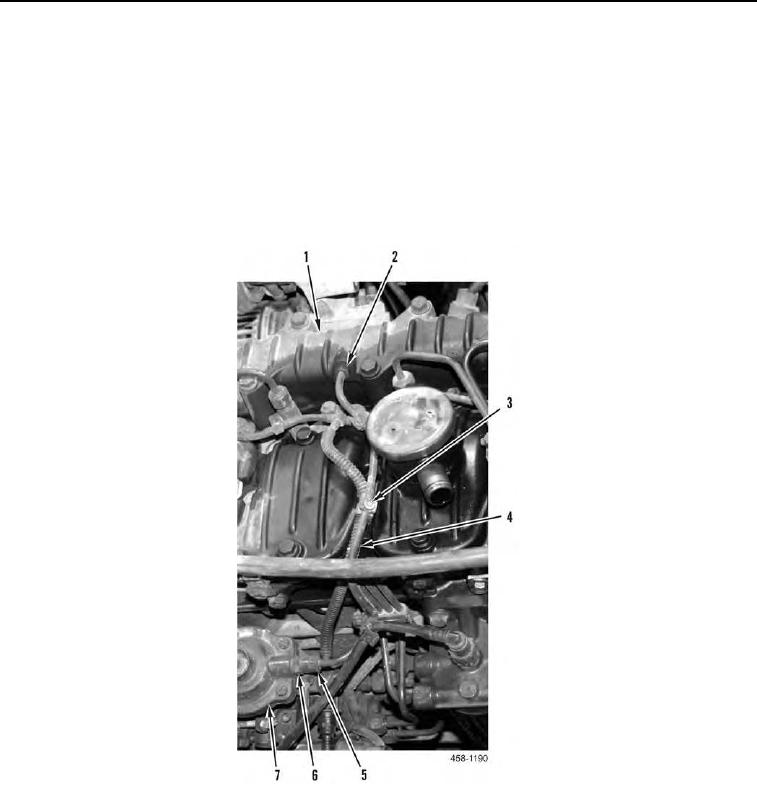
2. Disconnect fitting (Figure 2, Item 2) from intake manifold (Figure 2, Item 1).
3. Hold fitting (Figure 2, Item 6) and disconnect fitting (Figure 2, Item 5) from fuel injection pump (Figure 2,
Item 7).
4. Release hose (Figure 2, Item 4) from two clips (Figure 2, Item 3) and remove from machine.
5. Remove fitting (Figure 2, Item 6) from fuel injection pump (Figure 2, Item 7).
Figure 2. Hose.
0042