
TM 5-3805-292-23
0042
INSTALLATION CONTINUED
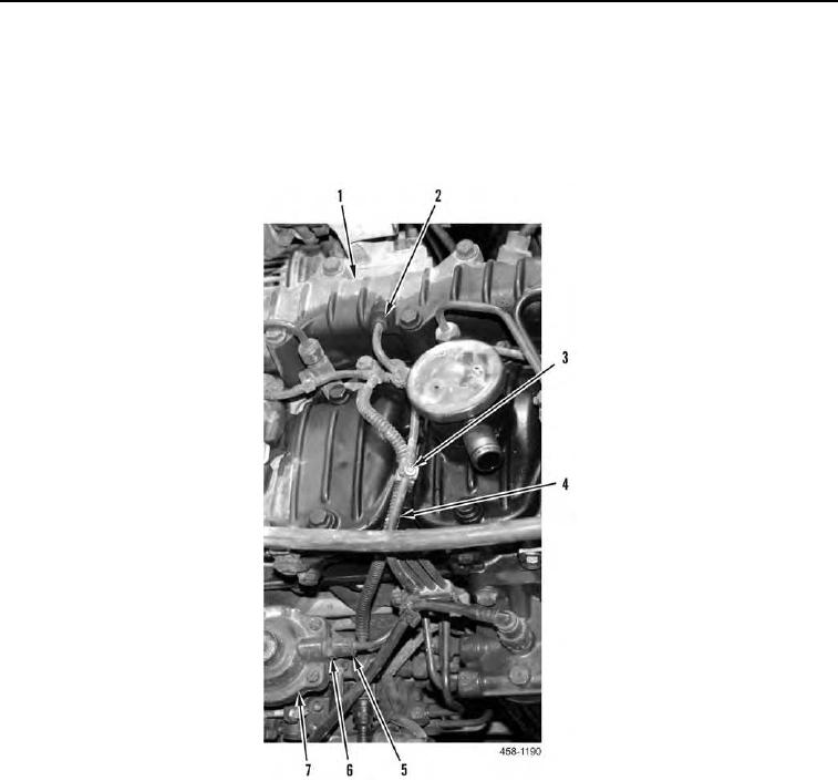
8. Install hose (Figure 7, Item 4) on machine and secure with two clips (Figure 7, Item 3).
9. Install fitting (Figure 7, Item 6) on fuel injection pump (Figure 7, Item 7).
10. Connect fitting (Figure 7, Item 5) to fuel injection pump (Figure 7, Item 7).
11. Connect fitting (Figure 7, Item 2) to intake manifold (Figure 7, Item 1).
Figure 7. Hose.
0042