
TM 5-3805-292-23
0043
CLEANING AND INSPECTION CONTINUED
WARN I N G
Particles blown by compressed air are hazardous. DO NOT exceed 15 psi (103 kPa)
nozzle pressure when drying parts with compressed air. DO NOT direct compressed air
against human skin. Make sure air stream is directed away from user and other personnel
in the area. To prevent injury, user must wear protective goggles or face shield. Failure to
follow this warning may result in injury to personnel.
3. Dry parts with compressed air.
4. Inspect parts for wear, pitting, cracks, or corrosion and replace if necessary.
END OF TASK
INSTALLATION
00043
N OT E
This procedure installs one fuel injector.
Repeat this procedure to insall additional fuel injectors.
t
Position fuel injector as noted during removal.
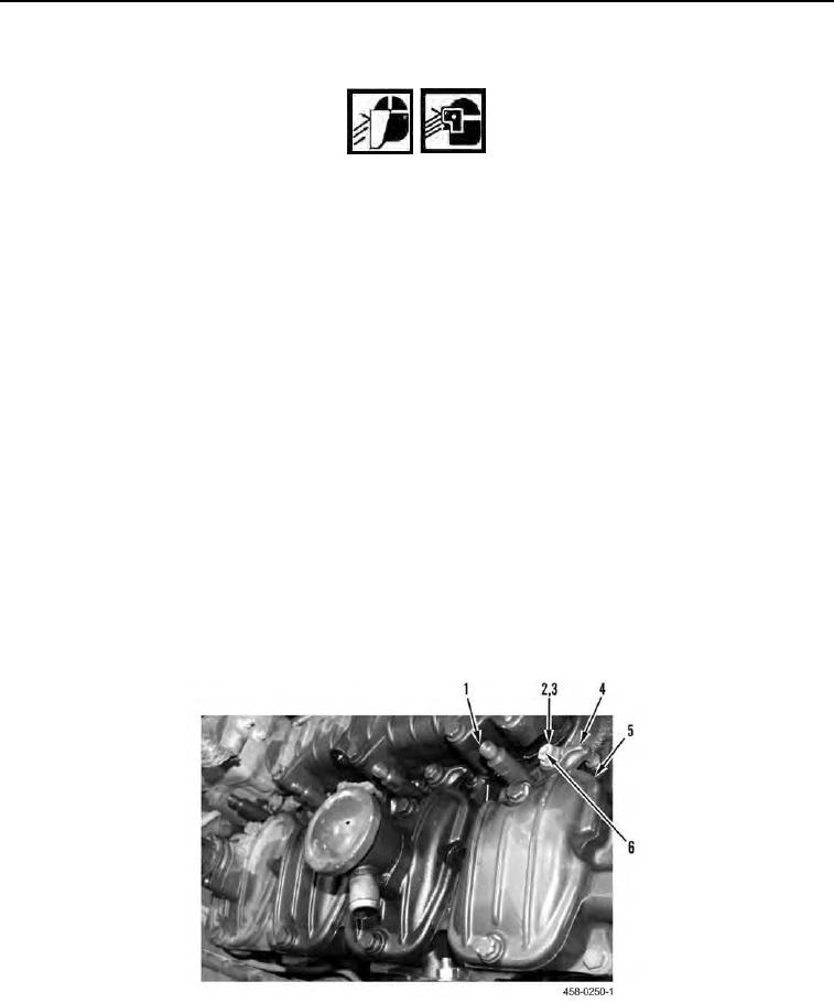
1. If removed, install stud (Figure 2, Item 6) on engine (Figure 2, Item 5).
2. Install fuel injector (Figure 2, Item 1) and bracket (Figure 2, Item 4) on engine (Figure 2, Item 5).
N OT E
Beveled side of washer faces bracket.
3. Install washer (Figure 2, Item 3) and nut (Figure 2, Item 2) on engine (Figure 2, Item 5).
Figure 2. Fuel Injectors.
0043
END OF TASK