
TM 5-3805-292-23
0044
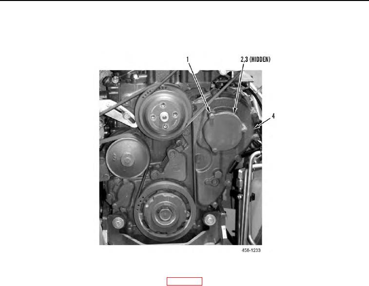
REMOVAL CONTINUED
4. Remove three bolts (Figure 3, Item 1), cover (Figure 3, Item 2), and O-ring (Figure 3, Item 3) from front cover
(Figure 3, Item 4). Discard O-ring.
Figure 3. Front Cover.
0044
5. Place engine in top dead center (TDC) position (WP 0057).
6. Loosen bolt (Figure 4, Item 8) and remove shim (Figure 4, Item 9). Save shim for installation.
7. Tighten bolt (Figure 4, Item 8) to lock fuel injection pump in correct position.
N OT E
Gear will remain in front housing when fuel injection pump is removed.
8. Remove nut (Figure 4, Item 1) and washer (Figure 4, Item 2) from gear (Figure 4, Item 3).
9. Remove three nuts (Figure 4, Item 10) from studs (Figure 4, Item 5).
10. With assistance, install fuel injection pump removal tool on gear (Figure 4, Item 3) and press gear off of pump
shaft.
11. Remove fuel injection pump (Figure 4, Item 7) and gasket (Figure 4, Item 6) from housing (Figure 4, Item 4).
Discard gasket.
12. Remove fuel injection pump removal tool from gear (Figure 4, Item 3).