• Home
  • Download PDF
  • Order CD-ROM
  • Order in Print
Figure 6. Front Cover.
Figure 8. Fuel Injection Pump.

Field Maintenance Manual For M400T And M400W
Page Navigation
  356    357    358    359    360  361  362    363    364    365    366  
img
.
TM 5-3805-292-23
0044
INSTALLATION CONTINUED
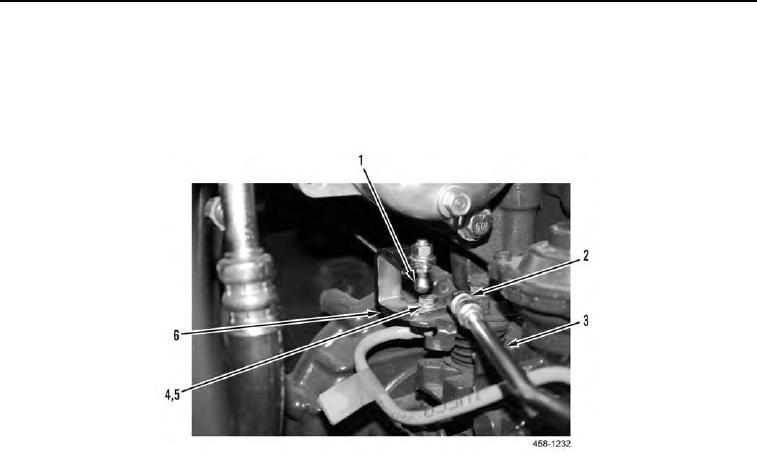
8. Install actuator (Figure 7, Item 6), two new lockwashers (Figure 7, Item 5), and bolts (Figure 7, Item 4) on
engine.
9. Pull back on sleeve (Figure 7, Item 2) and install throttle linkage (Figure 7, Item 3) on ball stud (Figure 7, Item
1).
Figure 7. Actuator-to-Engine Throttle Linkage (Rear).
0044
0044-9


Privacy Statement
Press Release
Contact

© Copyright Integrated Publishing, Inc.. All Rights Reserved.