• Home
  • Download PDF
  • Order CD-ROM
  • Order in Print
Figure 5. Fuel Injection Pump.
Figure 7. Actuator-to-Engine Throttle Linkage (Rear).

Field Maintenance Manual For M400T And M400W
Page Navigation
  355    356    357    358    359  360  361    362    363    364    365  
img
. .
TM 5-3805-292-23
0044
INSTALLATION CONTINUED
6. Take engine out of top dead center (TDC) (WP 0057).
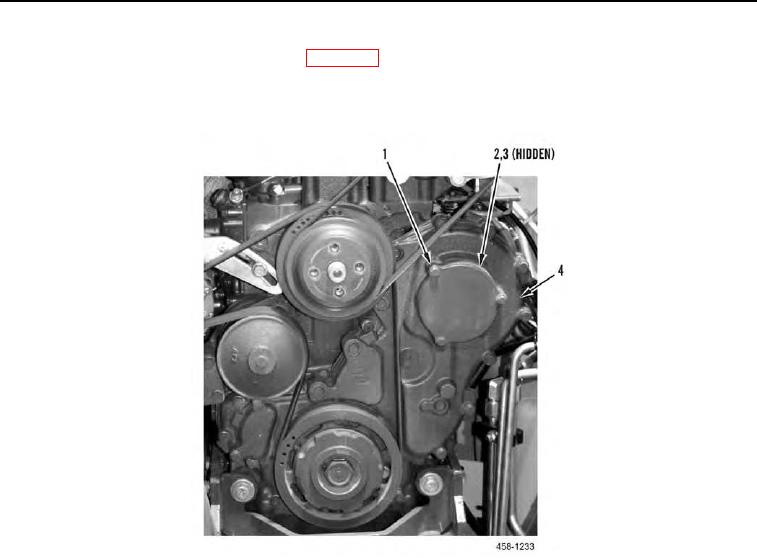
7. Install new O-ring (Figure 6, Item 3), cover (Figure 6, Item 2), and three bolts (Figure 6, Item 1) on front cover
(Figure 6, Item 4).
Figure 6. Front Cover.
0044
0044-8


Privacy Statement
Press Release
Contact

© Copyright Integrated Publishing, Inc.. All Rights Reserved.