
TM 5-3805-292-23
0053
INSTALLATION CONTINUED
11. Install fitting (Figure 8, Item 2) on engine.
12. Connect hose (Figure 8, Item 3) to fitting (Figure 8, Item 2) and install clamp (Figure 8, Item 1).
1
2
3
458-1100
Figure 8. Heater Hose Return.
0053
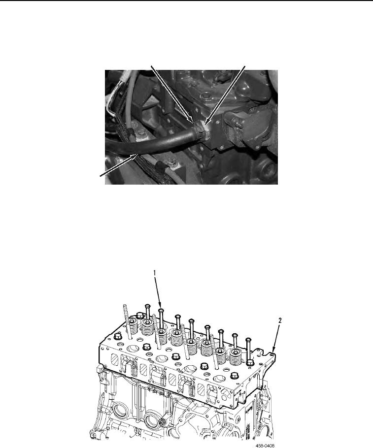
N OT E
Install push rods as noted during removal.
13. Install eight push rods (Figure 9, Item 1) on cylinder head (Figure 9, Item 2).
Figure 9. Push Rods.
0053
END OF TASK