
TM 5-3805-292-23
0053
REMOVAL CONTINUED
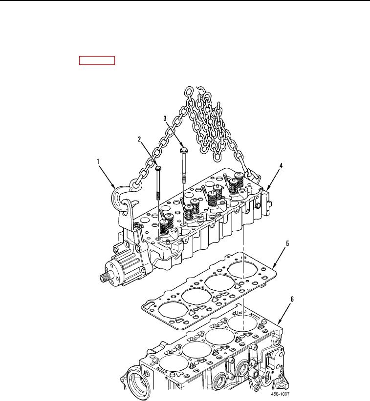
7. Using lifting device (Figure 4, Item 1) remove cylinder head assembly (Figure 4, Item 4) and gasket (Figure 4,
Item 5) from engine (Figure 4, Item 6). Discard gasket.
8. Place cylinder head assembly (Figure 4, Item 4) on work surface and remove lifting device (Figure 4, Item 1).
9. Remove fan support (WP 0054).
Figure 4. Cylinder Head.
0053
END OF TASK