• Home
  • Download PDF
  • Order CD-ROM
  • Order in Print
Figure 6. Cylinder Head Torque Sequence.
Figure 8. Heater Hose Return.

Field Maintenance Manual For M400T And M400W
Page Navigation
  393    394    395    396    397  398  399    400    401    402    403  
img
.
TM 5-3805-292-23
0053
INSTALLATION CONTINUED
N OT E
Install wire as tagged during removal.
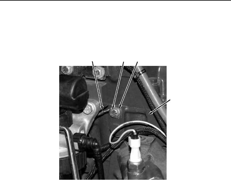
10. Install wire (Figure 7, Item 1), washer (Figure 7, Item 3), and bolt (Figure 7, Item 2) on cylinder head (Figure 7,
Item 4).
3
1
2
4
458-1101
Figure 7. Engine Harness.
0053
0053-9


Privacy Statement
Press Release
Contact

© Copyright Integrated Publishing, Inc.. All Rights Reserved.