
10
TM 5-3805-292-23
FIELD MAINTENANCE
-
ROCKER UNIT MAINTENANCE
0055
REMOVAL, DISASSEMBLY, CLEANING AND INSPECTION, ASSEMBLY, INSTALLATION
INITIAL SETUP
References
Tools and Special Tools
0
0
Tool Kit, General Mechanic's (WP 0178, Item
TM 5-3805-292-10
0
33)
TM 5-3805-292-23P, Figure 10
0
0
SATS (WP 0178, Item 30)
0
0
Wrench, Torque, Click, Ratcheting, 3/8 in.
Equipment Conditions
Drive, 75 lb-ft (contained in SATS) (WP
0
Machine parked on level ground
0178, Item 39)
0
0
ROPS tilted (WP 0134)
0
Materials/Parts
0
Valve covers removed (WP 0049)
0
Cleaning Compound, Solvent, Type III (WP
Fuel filter head removed (WP 0040)
0
0179, Item 3)
0
Fuel injection lines removed (WP 0042)
0
Rag, Wiping (WP 0179, Item 19)
0
Fuel injectors removed (WP 0043)
0
O-Ring
0
Intake manifold removed (WP 0045)
0
Gasket (2)
0
Plugs (3)
Estimated Time to Complete
0
0
7.3 Hr
0
REMOVAL
00055
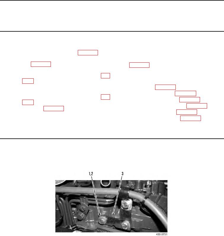
1. Remove two bolts (Figure 1, Item 1), washers (Figure 1, Item 2), and bracket (Figure 1, Item 3) from right side
of engine.
Figure 1. Air Duct Heater Bracket.
0055