
TM 5-3805-292-23
0069
DISASSEMBLY
00069
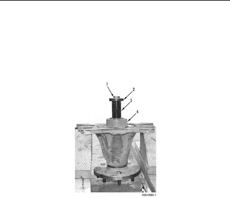
1. Support hub assembly (Figure 4, Item 4) so that axle (Figure 4, Item 3) is free to fall.
WARN I N G
Do not attempt to remove axle from hub without installing bolt and spacer, or axle could
drop out. Failure to follow this warning may result in injury to personnel, damage to
equipment or both.
2. Install bolt (Figure 4, Item 1) and spacer (Figure 4, Item 2) in axle shaft (Figure 4, Item 3).
3. Apply force to bolt (Figure 4, Item 1) to remove axle (Figure 4, Item 3) from wheel hub (Figure 4, Item 4).
4. Remove bolt (Figure 4, Item 1) and spacer (Figure 4, Item 2) from axle shaft (Figure 4, Item 3).
Figure 4. Axle Removal.
0069