
TM 5-3805-292-23
0069
DISASSEMBLY CONTINUED
N OT E
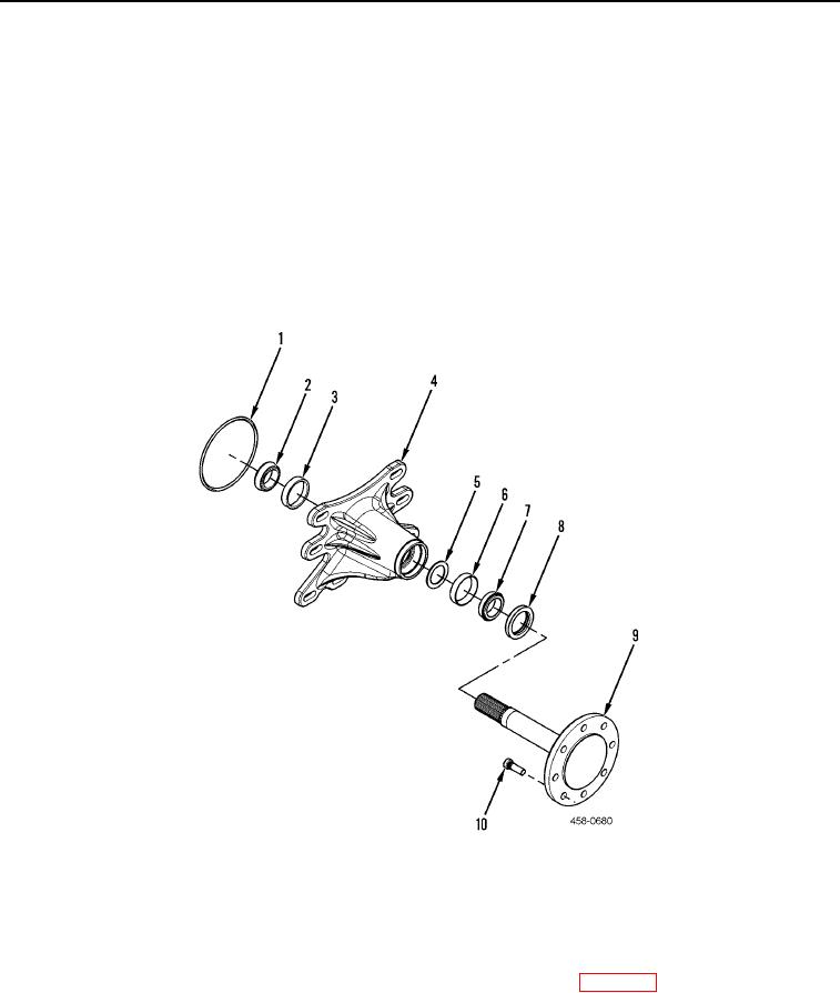
Do not remove tapered roller cones (Figure 5, Items 2 and 7) or spacer (Figure 5, Item 5)
unless damaged.
Do not mix tapered roller cones and tapered roller cups. Cones and cups must be
replaced as a set.
5. Remove O-ring (Figure 5, Item 1), tapered roller cone (Figure 5, Item 2), tapered roller cup (Figure 5, Item 3),
axle shaft (Figure 5, Item 9), seal (Figure 5, Item 8), tapered roller cone (Figure 5, Item 7), tapered roller cup
(Figure 5, Item 6), and spacer (Figure 5, Item 5) from wheel hub (Figure 5, Item 4). Discard O-ring, seal, and
spacer.
6. If damaged, remove and discard eight studs (Figure 5, Item 10) from axle shaft (Figure 5, Item 9).
Figure 5. Axle and Hub.
0069
END OF TASK
CLEANING AND INSPECTION
00069
Clean and inspect all parts IAW Mechanical General Maintenance Instructions (WP 0172).
END OF TASK