TM 5-3805-292-23
0069
ADJUSTMENT
00069
1. Remove chain tank cover.
N OT E
The deflection of the chains cannot be measured with accuracy.
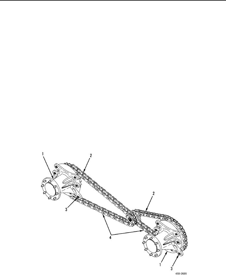
2. Check deflection of drive chains (Figure 10, Item 4) on slack side (Figure 10, Item 2). Slack side is on top of
front chain and on bottom of rear chain when traveling forward. Estimate amount of deflection by moving chain
up and down. If deflection is more than 1.5 in. (38 mm) for one chain, adjust deflection of chains.
3. Loosen axle hub assembly (Figure 10, Item 1) and nuts (Figure 10, Item 3) so axle is free to move.
4. Insert a pry bar against adjusting stud and axle hub assembly (Figure 10, Item 1).
5. Pry against axle hub assembly (Figure 10, Item 1) until it stops moving. Tighten one or two nuts (Figure 10,
Item 3) to hold axle hub assembly in place and check chain deflection (Figure 10, Item 2).
6. When chain deflection (Figure 10, Item 2) is 0.12 to 0.50 in. (3.0 to 12.7 mm), tighten nuts (Figure 10, Item 3)
to 5 lb-ft (7 Nm).
7. Repeat steps 1 through 6 for remaining drive chains (Figure 10, Item 4).
8. Following adjustment of drive chains (Figure 10, Item 4), start engine and run at low idle (TM 5-3805-292-10).
9. Move drive control handle fully forward for 5 seconds and stop engine (TM 5-3805-292-10).
10. Check deflection of drive chains (Figure 10, Item 4). Drive chains are correctly adjusted if deflection is 0.12 to
0.50 in. (3.0 to 12.7 mm).
11. If required, tighten or loosen drive chains (Figure 10, Item 4) to obtain correct deflection.
12. Tighten nuts (Figure 10, Item 3) to 165 to 195 lb-ft (224 to 264 Nm).
13. Install chain tank cover.
Figure 10. Chain Deflection.
0069
END OF TASK

