
TM 5-3805-292-23
0070
REMOVAL
00070
N OT E
Tag electrical connectors to aid in installation.
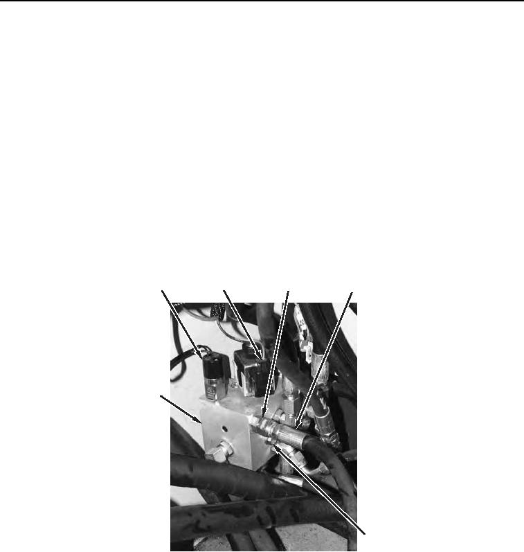
1. Place a clean rag under brake pilot valve (Figure 1, Item 7).
2. Remove two electrical connectors (Figure 1, Item 2) from brake pilot valve (Figure 1, Item 7).
3. Disconnect electrical connector (Figure 1, Item 1) from wiring harness.
N OT E
Tag all hoses and linesto aid in installation.
Cap fittings and hoses.
4. Loosen 10 fittings (Figure 1, Item 3) and remove 10 hoses (Figure 1, Item 4) from brake pilot valve (Figure 1,
Item 7).
5. Remove two bolts (Figure 1, Item 5) and four flat washers (Figure 1, Item 6) from brake pilot valve (Figure 1,
Item 7).
6. Remove brake pilot valve (Figure 1, Item 7) from machine.
1
4
3
2
7
5,6
458-0770
Figure 1. Brake Pilot Valve.
0070