
TM 5-3805-292-23
0070
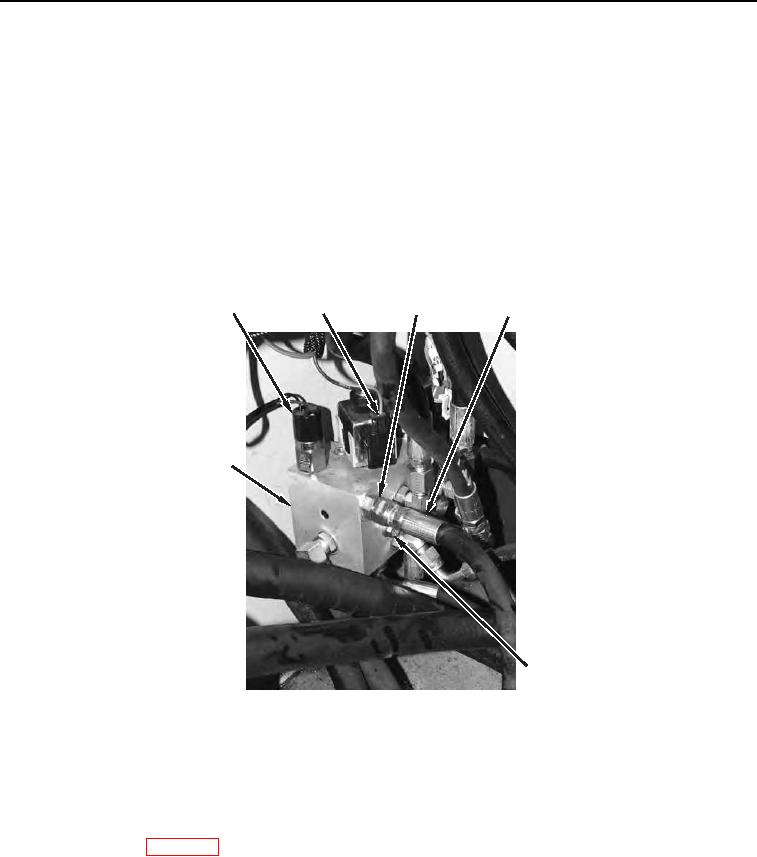
INSTALLATION CONTINUED
5. Position brake pilot valve (Figure 4, Item 7) on machine.
6. Install four flat washers (Figure 4, Item 6) and two bolts (Figure 4, Item 5) on brake pilot valve (Figure 4,
Item 7).
N OT E
Install hoses as noted during removal.
7. Connect 10 hoses (Figure 4, Item 4) to 10 fittings (Figure 4, Item 3) on brake pilot valve (Figure 4, Item 7).
Tighten fittings.
8. Connect two electrical connectors (Figure 4, Item 2) to brake pilot valve (Figure 4, Item 7).
9. Connect electrical connectors (Figure 4, Item 1) to wiring harness.
1
4
3
2
7
5,6
458-0770
Figure 4. Brake Pilot Valve.
0070
END OF TASK
FOLLOW-ON TASKS
00070
1. Install gear pump (WP 0088).
2. Verify correct operation of machine (TM 5-3805-292-10).
END OF TASK
END OF WORK PACKAGE