
TM 5-3805-292-23
0079
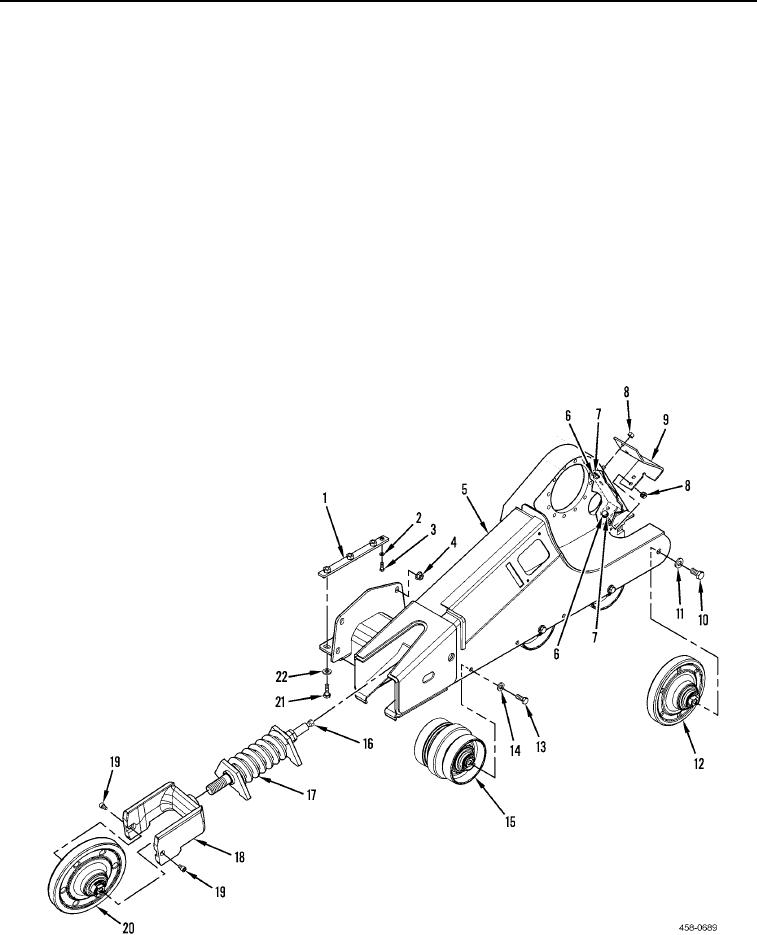
INSTALLATION CONTINUED
2. With assistance, install frame (Figure 7, Item 5) and eight nuts (Figure 7, Item 4) on machine.
3. Position two bars (Figure 7, Item 1) on machine and install eight washers (Figure 7, Items 2 and 22) and bolts
(Figure 7, Items 3 and 21).
4. Install grease fitting (Figure 7, Item 16) on tensioner (Figure 7, Item 17).
5. With assistance, install tensioner (Figure 7, Item 17), yoke (Figure 7, Item 18), and idler (Figure 7, Item 20), on
frame (Figure 7, Item 5).
6. With assistance, install idler (Figure 7, Item 20), and two screws (Figure 7, Item 19) on yoke (Figure 7, Item
17).
7. With assistance, install three rollers (Figure 7, Item 15), six washers (Figure 7, Item 14), and bolts (Figure 7,
Item 13) on frame (Figure 7, Item 5).
8. With assistance, install idler (Figure 7, Item 12), two washers (Figure 7, Item 11), and bolts (Figure 7, Item 10)
on frame (Figure 7, Item 5).
9. Install scraper (Figure 7, Item 9), four washers (Figure 7, Item 7), bolts (Figure 7, Item 6) and nuts (Figure 7,
item 8), on frame (Figure 7, Item 5).
Figure 7. Track Frame Assembly.
0079