• Home
  • Download PDF
  • Order CD-ROM
  • Order in Print
Figure 3. Lift Cylinder Upper Pin.
Figure 5. Lift Cylinder.

Field Maintenance Manual For M400T And M400W
Page Navigation
  591    592    593    594    595  596  597    598    599    600    601  
img
.
TM 5-3805-292-23
0086
REMOVAL CONTINUED
N OT E
Mark pin to aid in alignment for installation.
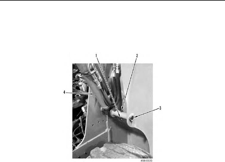
7. Remove nut (Figure 4, Item 1), bolt (Figure 4, Item 2), pin (Figure 4, Item 3), and lift cylinder (Figure 4, Item 4)
from machine.
Figure 4. Lift Cylinder Lower Pin.
0086
END OF TASK
0086-5


Privacy Statement
Press Release
Contact

© Copyright Integrated Publishing, Inc.. All Rights Reserved.