
TM 5-3805-292-23
0100
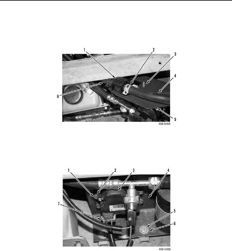
INSTALLATION CONTINUED
6. Position valve (Figure 15, Item 1) on bracket (Figure 15, Item 5) and install four bolts (Figure 16, Item 1), new
lockwashers (Figure 16, Item 2), and nuts (Figure 15, Item 3).
7. Connect hoses (Figure 15, Items 4 and 6) to valve (Figure 15, Item 1) and install two clamps (Figure 15,
Item 2).
Figure 15. Electric Water Valve (Rear).
0100
8. Position bracket (Figure 16, Item 4) and install two washers (Figure 16, Item 6) and bolts (Figure 16, Item 5) on
bracket.
9. Connect electrical connector (Figure 16, Item 7) to valve (Figure 16, Item 3).
Figure 16. Electric Water Valve (Front).
0100