
TM 5-3805-292-23
0100
INSTALLATION CONTINUED
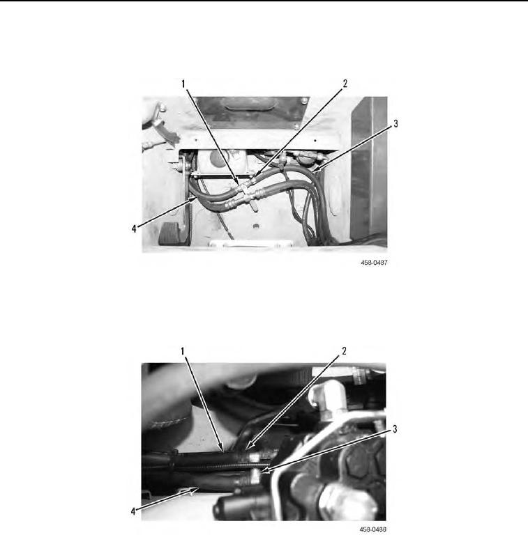
10. Position valve (Figure 17, Item 1) on machine, connect hoses (Figure 17, Items 3 and 4) to valve, and install
two clamps (Figure 17, Item 2) on hoses.
Figure 17. Heater ON/OFF Valve.
0100
11. Position splice fitting (Figure 18, Item 3) on machine, connect four hoses (Figure 18, Items 1 and 4) to splice
fitting, and install four clamps (Figure 18, Item 2) on hoses.
Figure 18. Heater Hose Splice.
0100