
TM 5-3805-292-23
0100
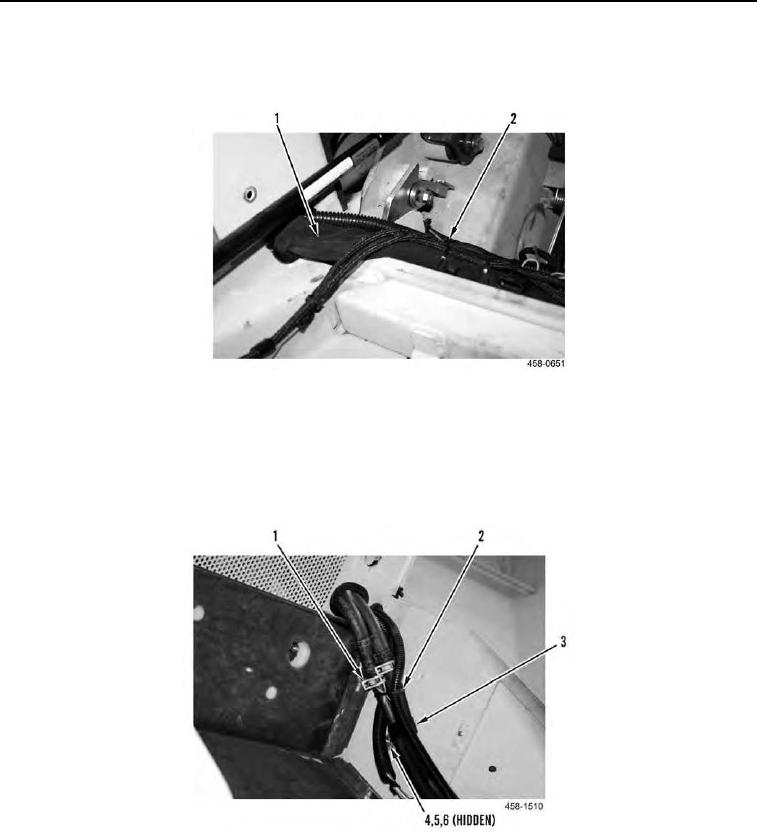
REMOVAL CONTINUED
15. Remove all tiedown straps (Figure 8, Item 2) and sheath (Figure 8, Item 1) from two hoses. Discard tiedown
straps.
Figure 8. Cab Front.
0100
16. Remove bolt (Figure 9, Item 4), nut (Figure 9, Item 5), washer (Figure 9, Item 6), and clamp (Figure 9, Item 3)
from machine.
17. Release two clamps (Figure 9, Item 1) and disconnect hoses (Figure 9, Item 2) from machine. Remove clamps
from hoses.
Figure 9. ROPS Rear.
0100