
TM 5-3805-292-23
0100
REMOVAL CONTINUED
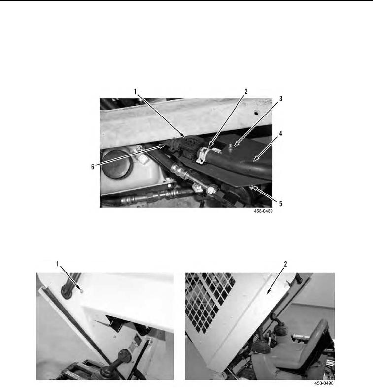
11. Tilt bracket (Figure 6, Item 5) forward, release two clamps (Figure 6, Item 2), and disconnect hoses (Figure 6,
Items 4 and 6) from valve (Figure 6, Item 1).
12. Remove hose (Figure 6, Item 6) from machine.
13. Remove four nuts (Figure 6, Item 3), bolts (Figure 5, Item 1), and lockwashers (Figure 5, Item 2) from bracket
(Figure 6, Item 5) and remove valve (Figure 6, Item 1) from machine. Discard lockwashers.
Figure 6. Electric Water Valve (Rear).
0100
14. Remove three bolts (Figure 7, Item 1) from interior of cab and remove cover (Figure 7, Item 2) from machine.
Figure 7. RH Hose Cover.
0100