
TM 5-3805-292-23
0106
ASSEMBLY CONTINUED
N OT E
Install hydraulic hoses as tagged during removal.
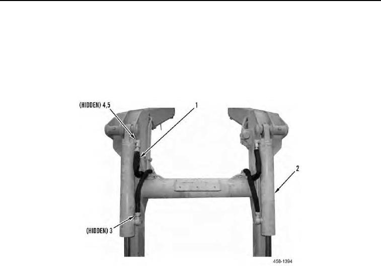
10. Install two new O-rings (Figure 15, Item 5) and fittings (Figure 15, Item 4) on tilt cylinders (Figure 15, Item 2).
11. Install four hydraulic hoses (Figure 15, Item 1) and two new O-rings (Figure 15, Item 3) on tilt cylinders (Figure
15, Item 2).
Figure 15. Hoses.
0106
END OF TASK