
TM 5-3805-292-23
0128
REMOVAL CONTINUED
Door Handle and Latch Assembly - Continued
000128
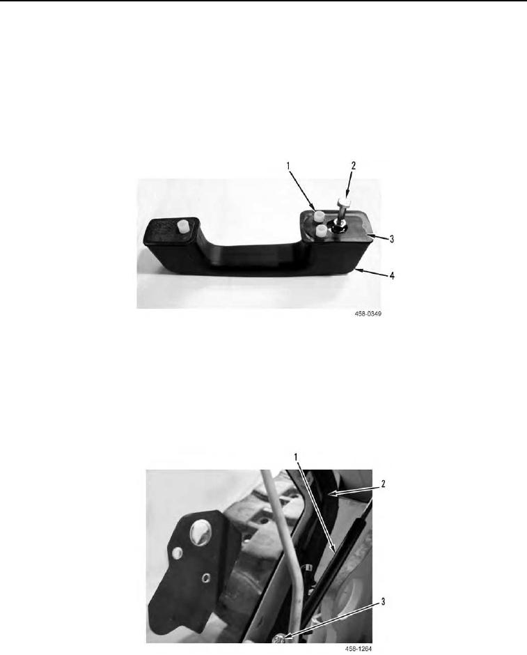
6. Remove door handle (Figure 10, Item 4), two gaskets (Figure 10, Item 3), and three spacers (Figure 10, Item
1) from exterior of front door. Discard gaskets.
N OT E
Bolt is a 1/4-20 UNC 2B capscrew and nut.
7. Remove bolt (Figure 10, Item 2) from door handle (Figure 10, Item 4).
Figure 10. Door Handle, Gaskets, and Spacers.
0128
END OF TASK
Front Door
000128
1. Remove shouldered nut (Figure 11, Item 3) from cylinder (Figure 11, Item 1). Repeat for other end of cylinder.
2. Remove seal (Figure 11, Item 2) from door.
Figure 11. Cylinder.
0128