
TM 5-3805-292-23
0128
INSTALLATION CONTINUED
Front Door - Continued
5. Install seal (Figure 17, Item 2) on door.
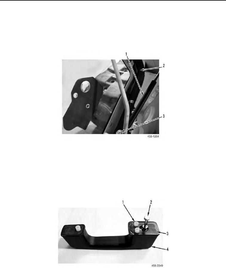
6. Position cylinder (Figure 17, Item 1) on front door interior and install shouldered nut (Figure 17, Item 2) on
cylinder. Repeat for other end of cylinder.
Figure 17. Cylinder.
0128
END OF TASK
Door Handle and Latch Assembly
000128
1. Install bolt (Figure 18, Item 2) on door handle (Figure 18, Item 4).
2. Position two new gaskets (Figure 18, Item 3), three spacers (Figure 18, Item 1), and door handle (Figure 18,
Item 4) on front door exterior.
Figure 18. Door Handle, Gaskets, and Spacers.
0128