
TM 5-3805-292-23
0146
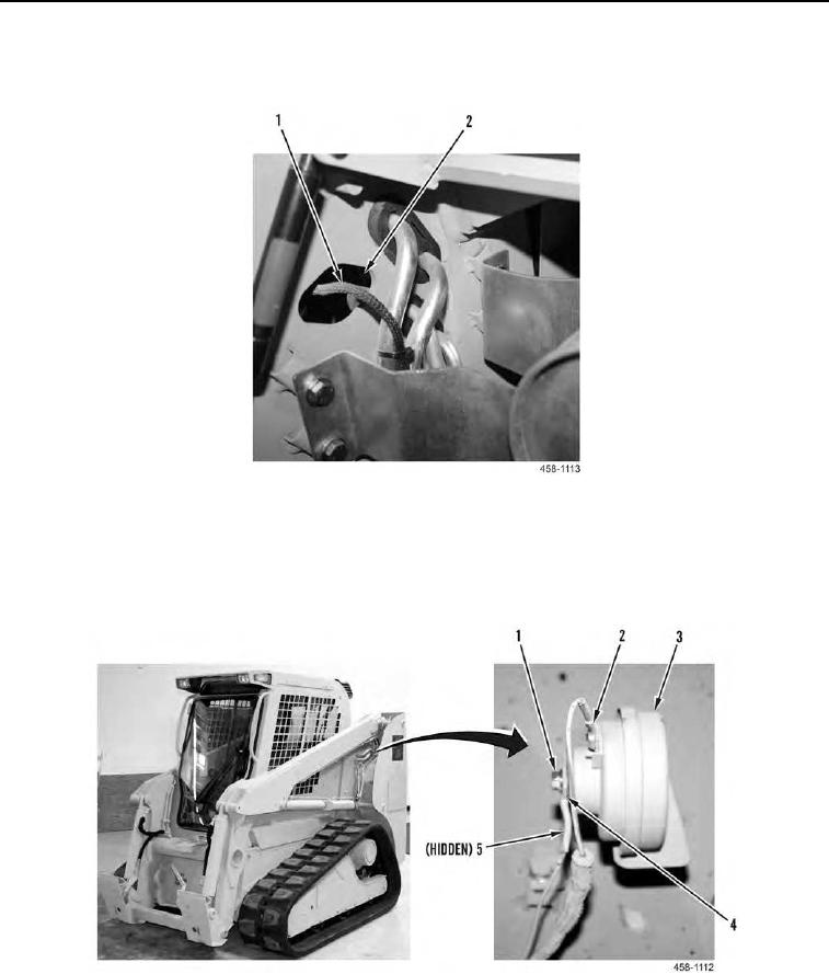
INSTALLATION CONTINUED
38. Pull horn wiring (Figure 34, Item 1) through opening (Figure 34, Item 2).
Figure 34. Horn Wiring.
0146
39. Install wire connector (Figure 35, Item 2) on horn (Figure 35, Item 3).
40. Install horn (Figure 35, Item 3), wire eyelet (Figure 35, Item 4), and nut (Figure 35, Item 1) on bracket (Figure
35, item 5).
.
Figure 35. Horn Wiring.
0146