
TM 5-3805-292-23
0146
INSTALLATION CONTINUED
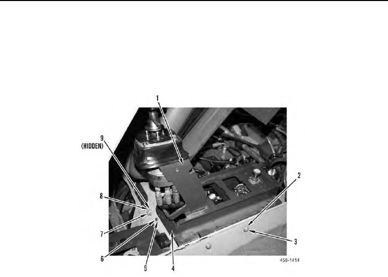
22. Position left hand joystick support (Figure 30, Item 1) on machine.
23. Install two washers (Figure 30, Item 2) and bolts (Figure 30, Item 3) on machine.
24. Install bolt (Figure 30, Item 7), washer (Figure 30, Item 8) and nut (Figure 30, Item 9) on left hand joystick sup-
port (Figure 30, Item 1).
25. Install plate (Figure 30, Item 4), washer (Figure 30, Item 5), and bolt (Figure 30, Item 6) on machine.
Figure 30. Left Joystick Support.
0146