• Home
  • Download PDF
  • Order CD-ROM
  • Order in Print
Figure 30. Left Joystick Support.
Figure 32. Hydraulic Pump Wiring.

Field Maintenance Manual For M400T And M400W
Page Navigation
  989    990    991    992    993  994  995    996    997    998    999  
img
.
TM 5-3805-292-23
0146
INSTALLATION CONTINUED
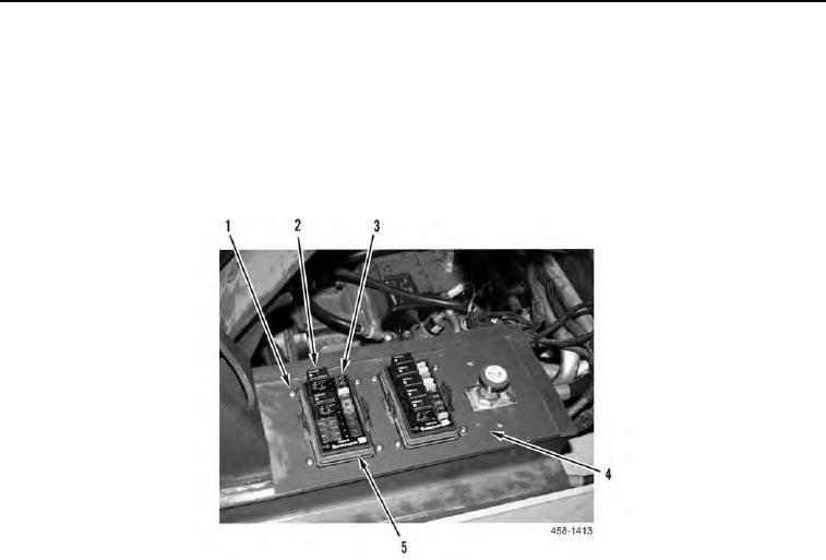
26. Install two fuse panels (Figure 31, Item 5) and eight screws (Figure 31, Item 1) on left joystick support (Figure
31, Item 4).
N OT E
Install fuses and relays as noted during removal.
27. Install fuses (Figure 31, Item 3) and relays (Figure 31, Item 2) into two fuse panels (Figure 31, Item 5).
Figure 31. Fuse Panel.
0146
0146-22


Privacy Statement
Press Release
Contact

© Copyright Integrated Publishing, Inc.. All Rights Reserved.