
TM 5-3805-292-23
0146
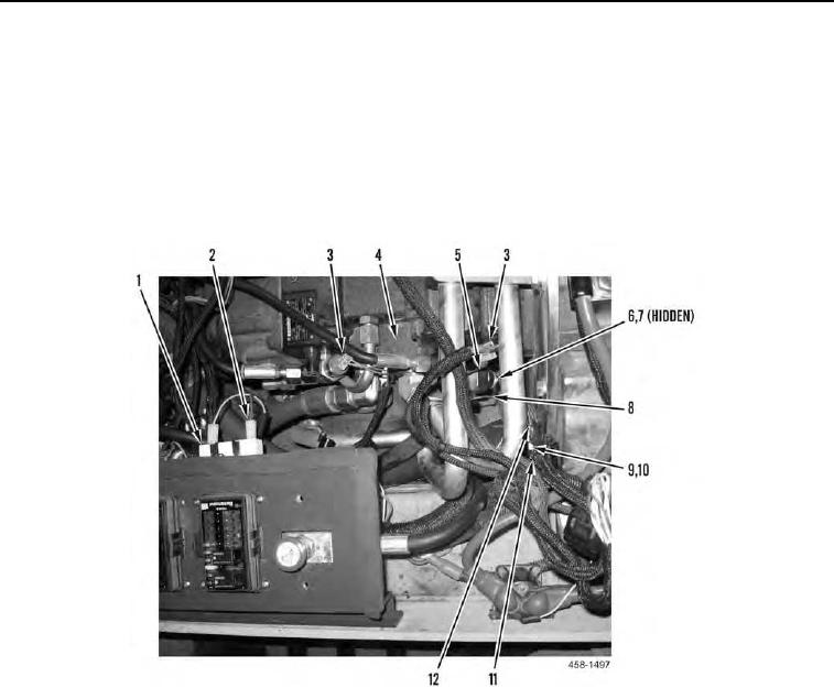
INSTALLATION CONTINUED
28. Connect two electrical connectors (Figure 32, Item 2) to charging system protection resistor (Figure 32, Item
1).
29. Install wire (Figure 32, Item 8), washer (Figure 32, Item 7), and nut (Figure 32, Item 6) on switch (Figure 32,
Item 5).
30. Install ground strap (Figure 32, Item 12), three ground eyelets (Figure 32, Items 11), washer (Figure 32, Item
10), and bolt (Figure 32, Item 9) on flywheel housing.
31. Connect four harness connectors (Figure 32, Item 3) to hydraulic pump (Figure 32, Item 4).
Figure 32. Hydraulic Pump Wiring.
0146