
TM 5-3805-292-23
0149
REMOVAL CONTINUED
N OT E
Tag and identify all electrical connections to aid in installation.
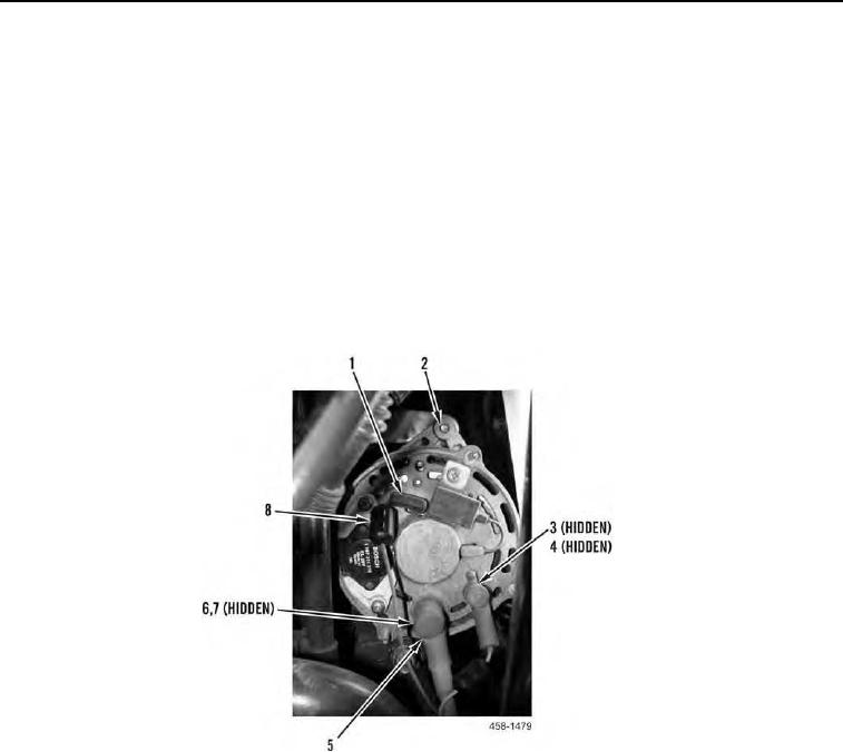
7. Position two rubber boots (Figure 4, Item 5) aside. Remove nut (Figure 4, Item 6) and lockwasher (Figure 4,
Item 7) from alternator. Discard lockwasher.
N OT E
Do not discard suppressors.
8. Remove nut (Figure 4, Item 3) and washer (Figure 4, Item 4) from alternator.
9. Remove three wires (Figure 4, Item 1) from alternator (Figure 4, Item 2).
10. Remove two suppressors (Figure 4, Item 8) from wires (Figure 4, Item 1).
Figure 4. Alternator Wiring.
0149
11. Remove nut (Figure 5, Item 1), washer (Figure 5, Item 2) and two wires (Figure 5, Item 4) from engine ground
stud (Figure 5, Item 3).