• Home
  • Download PDF
  • Order CD-ROM
  • Order in Print
Figure 10. Coolant Temperature Sending Unit (Parts Removed for Clarity).
Figure 13. Right Side Engine Wiring.

Field Maintenance Manual For M400T And M400W
Page Navigation
  1012    1013    1014    1015    1016  1017  1018    1019    1020    1021    1022  
img
.
TM 5-3805-292-23
0149
INSTALLATION CONTINUED
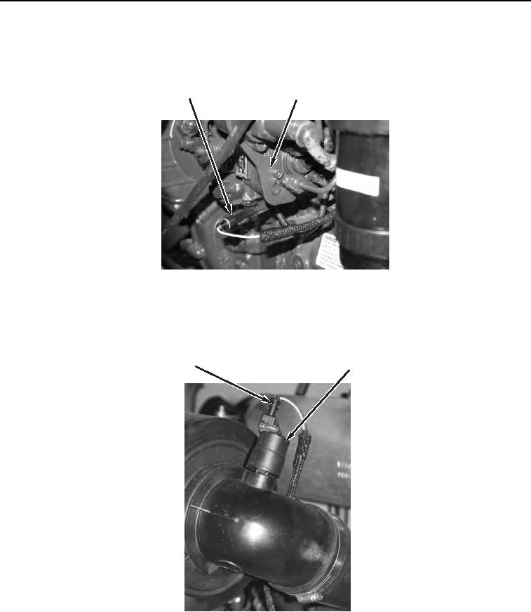
3. Connect electrical connector (Figure 11, Item 1) to fuel injection pump housing (Figure 11, Item 2).
2
1
458-1084
Figure 11. Electrical Connector at Fuel Injection Pump.
0149
4. Connect electrical connector (Figure 12, Item 1) to air filter restriction sensor (Figure 12, Item 2).
2
1
458-1083
Figure 12. Air Filter Restriction Sensor Connector.
0149
0149-9


Privacy Statement
Press Release
Contact

© Copyright Integrated Publishing, Inc.. All Rights Reserved.