
TM 5-3805-292-23
0149
INSTALLATION
000149
1. Position engine wiring harness on machine.
N OT E
Install tiedown straps as noted during removal.
Connect all electrical connections as noted during removal.
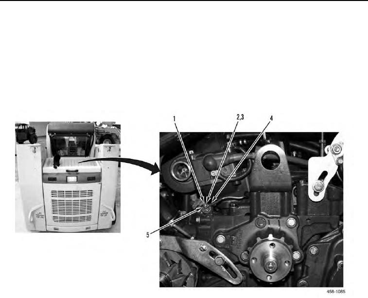
2. Install wire (Figure 10, Item 4), new lockwasher (Figure 10, Item 5), washer (Figure 10, Item 3) and nut (Figure
10, Item 2) on coolant temperature sending unit (Figure 10, Item 1).
Figure 10. Coolant Temperature Sending Unit (Parts Removed for Clarity).
0149