
TM 5-3805-292-23
0149
INSTALLATION CONTINUED
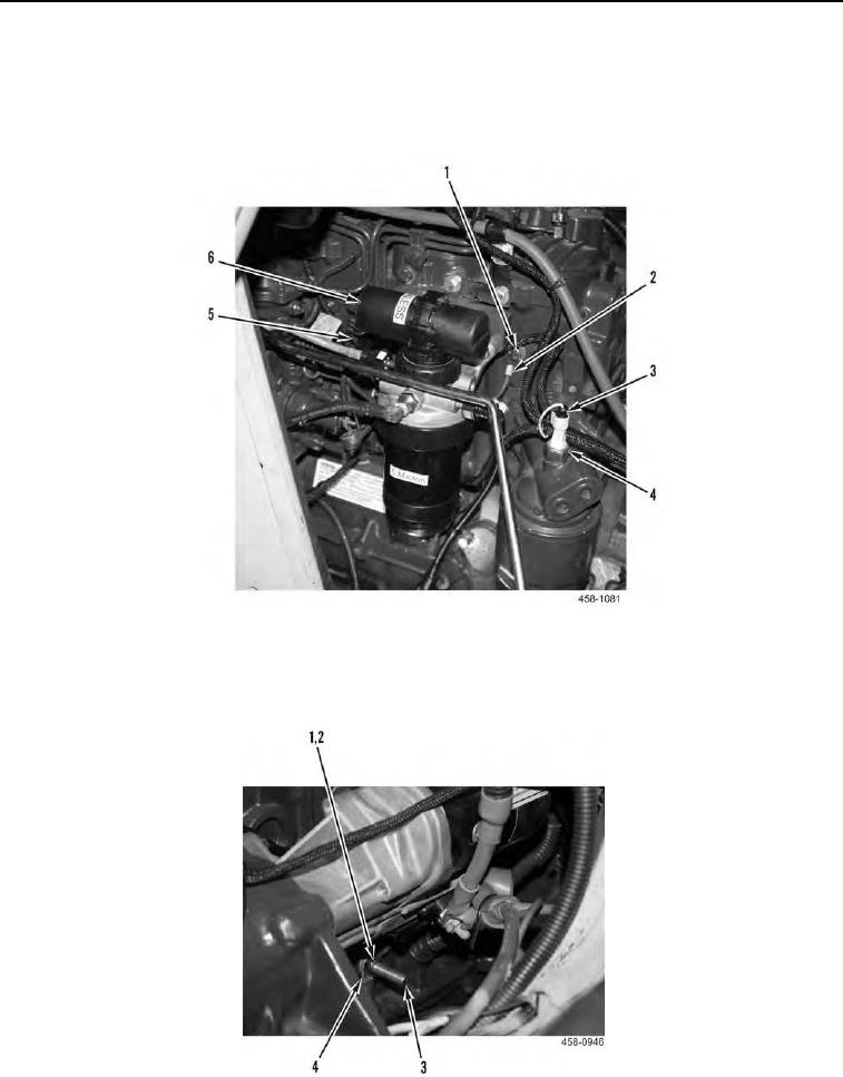
5. Connect electrical connector (Figure 13, Item 5) to fuel primer pump (Figure 13, Item 6).
6. Connect electrical connector (Figure 13, Item 3) to oil pressure sending unit (Figure 13, Item 4).
7. Install ground wire (Figure 13, Item 2), and bolt (Figure 13, Item 1) on engine block.
Figure 13. Right Side Engine Wiring.
0149
8. Install two wires (Figure 14, Item 4), washer (Figure 14, Item 2) and nut (Figure 14, Item 1) on engine ground
stud (Figure 14, Item 3).
Figure 14. Engine Ground Stud.
0149