
TM 5-3805-292-23
0149
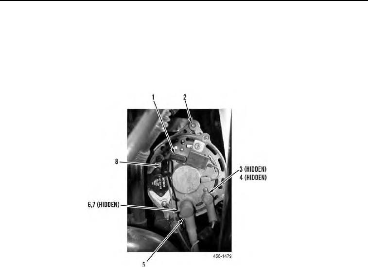
INSTALLATION CONTINUED
9. Install two suppressors (Figure 15, Item 8) on wires (Figure 15, Item 1).
10. Connect three wires (Figure 15, Item 1) to alternator (Figure 15, Item 2).
11. Install nut (Figure 15, Item 3) and washer (Figure 15, Item 4) on alternator.
12. Install new lockwasher (Figure 15, Item 7) and nut (Figure 15, Item 6) on alternator.
13. Slide rubber boots (Figure 15, Item 5) over terminals.
Figure 15. Alternator Wiring.
0149