
TM 5-3805-292-23
0166
INSTALLATION
000166
1. Install switch (Figure 3, Item 3) and nut (Figure 3, Item 2) on RH console (Figure 3, Item 4).
2. Install knob (Figure 3, Item 1) on switch (Figure 3, Item 3).
N OT E
Install wiring harness as tagged during removal.
3. Connect wiring harness (Figure 2, Item 1) to switch (Figure 2, Item 2).
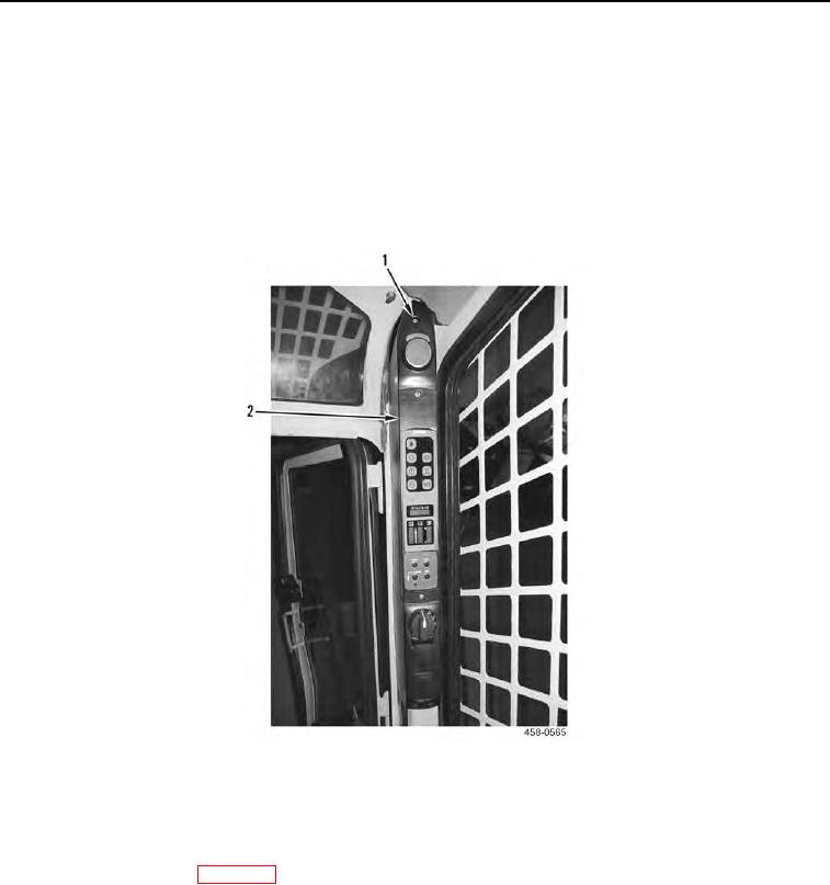
4. Install RH console (Figure 4, Item 2) and three screws (Figure 4, Item 1) on cab.
Figure 4. RH Console.
0166
END OF TASK
FOLLOW-ON TASKS
000166
1. Connect battery power (WP 0142).
2. Verify correct operation of machine (TM 5-3805-292-10).
END OF TASK
END OF WORK PACKAGE
0166-3/(4 blank)