
TM 5-3805-292-23
0171
DISASSEMBLY CONTINUED
Figure 4. Cylinder Hoses.
0171
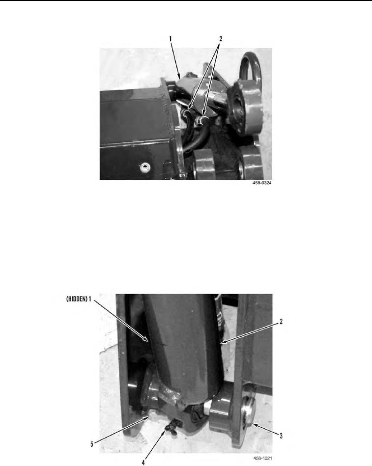
15. Remove grease fitting (Figure 5, Item 4) from cylinder (Figure 5, Item 2).
16. Remove capscrew (Figure 5, Item 5) and locknut (Figure 5, Item 1) from lower cylinder pin (Figure 5, Item 3).
Discard locknut.
17. Drive lower cylinder pin (Figure 5, Item 3) from assembly.
18. Remove cylinder (Figure 5, Item 2) from assembly.
19. Repeat steps 15 through 18 for other cylinder.
Figure 5. Lower Cylinder.
0171
0171-5