TM 5-3805-298-23-1
0007
Instrument Cluster Self-Test
0007
The instrument cluster performs a self-test each time the ignition switch is placed in the ON or START position (TM
5-3805-298-10). During the instrument cluster self-test, all gauge needles will move to the middle position for 0.5
seconds, then all gauge needles will move to the full left position, all indicators are illuminated, and the action alarm
will activate. Next, all gauge needles will move to the full right position, and all indicators and the action alarm turn
off. Finally, all gauges will move to the full left position, then move to a position based on actual values, and each
active indicator will illuminate.
Service Menu Self-Test
0007
The self-test will also be initiated when the service menu is entered. During the service menu self test all gauge
needles will move to the full right position, all indicators are illuminated, and the action alarm will activate. Next, all
indicators and action alarm will turn off, and all gauge needles will move to the full left position. Finally, each
indicator and gauge will illuminate or move to a position based on actual values.
Displaying Diagnostic Fault Codes
0007
Turn the ignition switch to the off position (TM 5-3805-298-10) for at least two minutes. Cycle the ignition switch
from the off position to the on position three times within 10 seconds, ending with the ignition switch in the on
position (TM 5-3805-298-10). The instrument cluster will enter the service menu, and the service menu self test will
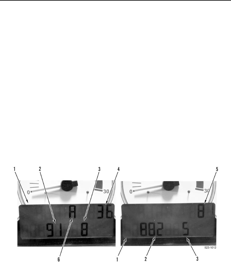
begin, then each diagnostic code will be displayed on the LCD screen (Figure 2, Item 1).
The LCD screen (Figure 2, Item 1) will display Module Identification (MID) 36 (Figure 2, Item 4) for the engine ECM
and 81 (Figure 2, Item 5) for the transmission ECM. The MID indicates which ECM is reporting the diagnostic fault
or event code. The LCD screen will display the letter A (Figure 2, Item 6) if the diagnostic fault code is active. Each
diagnostic fault code will be displayed for approximately three seconds and the next code will be displayed.
A diagnostic fault code consists of two groups of numbers. The first set of numbers is the component identifier
(CID) (Figure 2, Item 2). The second set of numbers is the failure mode identifier (FMI) (Figure 2, Item 3). Together,
these identify the component or system and the type of fault detected.
Figure 2. Diagnostic Code Display.
0007

