
TM 5-3805-298-23-2
0166
RELIEF VALVE PRESSURE FOR HEAD END TILT CYLINDER TEST CONTINUED
5. Remove right lower cab access panels (WP 0347).
6. Remove cap (Figure 42, Item 2) from head end of tilt cylinder pressure port (Figure 42, Item 1).
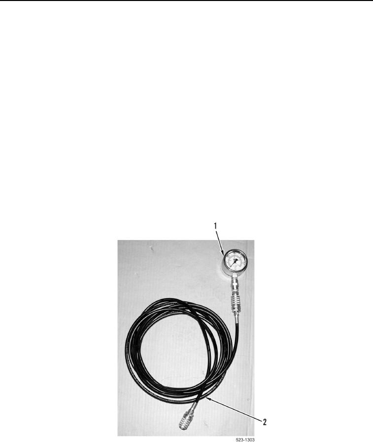
7. Connect other end of hose 177-7861 (Figure 41, Item 2) to head end of tilt cylinder pressure port
(Figure 42, Item 1).
8. Turn battery disconnect switch ON and have an assistant start engine (TM 5-3805-298-10).
9. Have an assistant run engine at high idle (2,450 rpm) (TM 5-3805-298-10).
10. Have an assistant bring the hydraulic oil to operating temperature 140F (60C) (TM 5-3805-298-10).
11. Have an assistant raise bucket lift half way up. Tilt the bucket forwards fully. Raise bucket slowly till tilt
cylinders retract (TM 5-3805-298-10).
12. Record the pressure on the 5,800 psi (40,000 kPa) gauge (Figure 41, Item 1).
13. Tilt the bucket level to the ground and lower the bucket to the ground (TM 5-3805-298-10).
14. Turn ignition switch and battery disconnect switch to OFF position (TM 5-3805-298-10).
15. Pressure reading should be 1,750 50 psi (12,066 345 kPa).
16. Disconnect hose 177-7861 (Figure 41, Item 2) from head end of tilt cylinder pressure port (Figure 42, Item 1).
17. Install cap (Figure 42, Item 2) on head end of tilt cylinder pressure port (Figure 42, Item 1).
18. Install right lower cab access panels (WP 0347).
Figure 41. 5,800 psi (40,000 kPa) Gauge Assembly.
0166
END OF TASK