
TM 5-3805-298-23-2
0166
SERVICE BRAKE SYSTEM PRESSURE TEST
000166
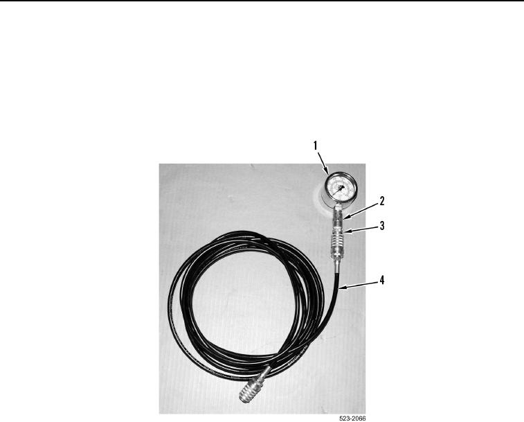
1. Apply sealant on threads of 3,600 psi (25,000 kPa) gauge (Figure 61, Item 1) and a 6V-3966 valved nipple
(Figure 61, Item 3) from pressure gauge kit.
2. Install adapter (Figure 61, Item 2) on 3,600 psi (25,000 kPa) gauge (Figure 61, Item 1).
3. Install 6V-3966 valved nipple (Figure 61, Item 3) on adapter (Figure 61, Item 2).
4. Connect hose 177-7861 (Figure 61, Item 4), from pressure gauge kit, to 6V-3966 valved nipple
(Figure 61, Item 3).
Figure 61. 3,600 psi (25,000 kPa) Gauge Assembly.
0166