
TM 5-3805-298-23-2
0166
SERVICE BRAKE SYSTEM PRESSURE TEST CONTINUED
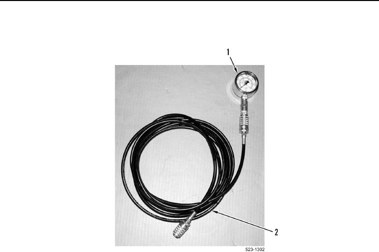
11. Connect other end of hose 177-7861 (Figure 64, Item 2) to front brake pressure port (Figure 63, Item 1).
Figure 64. 3,600 psi (25,000 kPa) Gauge Assembly.
0166
12. Turn battery disconnect switch ON and have an assistant start engine (TM 5-3805-298-10).
13. Have an assistant bring the hydraulic oil to operating temperature 140F (60C) (TM 5-3805-298-10).
14. Have an assistant run engine at low idle (TM 5-3805-298-10).
15. Have an assistant press and hold brake pedal (TM 5-3805-298-10).
16. Record the pressure on the 3,600 psi (25,000 kPa) gauge (Figure 64, Item 1).
17. Pressure reading should be 810 62 psi (5,600 430 kPa).
18. Release brake pedal (TM 5-3805-298-10).
19. Turn ignition switch and battery disconnect switch to OFF position (TM 5-3805-298-10).
20. Disconnect hose 177-7861 (Figure 64, Item 2) from front brake pressure port (Figure 63, Item 1).
21. Install cap (Figure 63, Item 2) on front brake pressure port (Figure 63, Item 1).
END OF TASK
END OF WORK PACKAGE
0166-69/(70 blank)