
TM 5-3805-298-23-2
0177
REMOVAL
000177
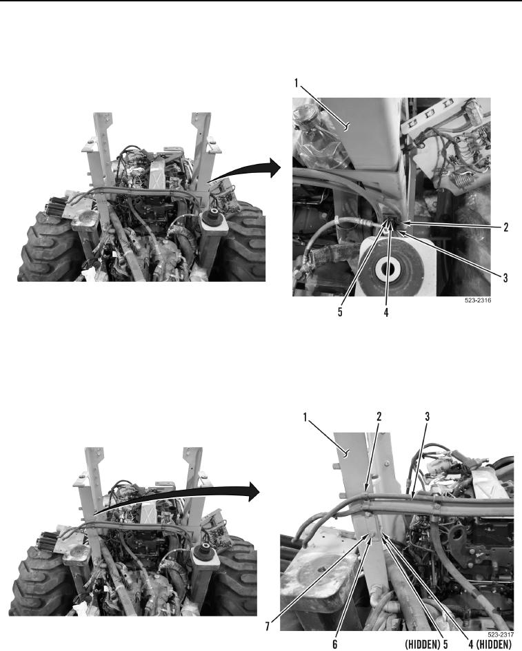
1. Remove bolt (Figure 1, Item 4), washer (Figure 1, Item 5), P-clamp (Figure 1, Item 2) and bracket (Figure 1,
Item 3) from left hydraulic tank support bracket (Figure 1, Item 1).
Figure 1. Left Hydraulic Tank Support Bracket.
0177
2. Remove two nuts (Figure 2, Item 4), washers (Figure 2, Item 5), bolts (Figure 2, Item 6), washers (Figure 2,
Item 7), P-clamps (Figure 2, Item 2) and bracket (Figure 2, Item 3) from right hydraulic tank support bracket
(Figure 2, Item 1). Position bracket aside.
Figure 2. Right Hydraulic Tank Support Bracket.
0177