TM 5-3805-298-23-2
0177
REMOVAL CONTINUED
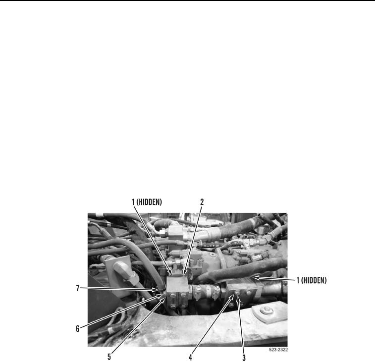
9. Remove bolt (Figure 6, Item 6), washer (Figure 6, Item 5) and ladder clip (Figure 6, Item 7) from manifold
assembly (Figure 6, Item 2).
CAUTION
Cap all hydraulic openings along with component connections during removal to protect
against contamination. Failure to follow this caution may result in damage to equipment.
NOTE
Tag and mark all hoses and tubes to aid in installation.
Note routing of hoses and tubes for installation.
There is not sufficient clearance to remove lower bolts from steering pump manifold and
implement pump manifold. They must be loosened and then removed with manifolds
when upper bolts are removed.
10. Remove eight bolts (Figure 6, Item 3), washers (Figure 6, Item 4), two O-rings (Figure 6, Item 1) and manifold
assembly (Figure 6, Item 2) from machine. Discard O-rings.
Figure 6. Manifold Assembly.
0177

