
TM 5-3805-298-23-2
0177
REMOVAL CONTINUED
CAUTION
Cap all hydraulic openings along with component connections during removal to protect
against contamination. Failure to follow this caution may result in damage to equipment.
NOTE
Tag and mark all hoses and tubes to aid in installation.
Note routing of hoses and tubes for installation.
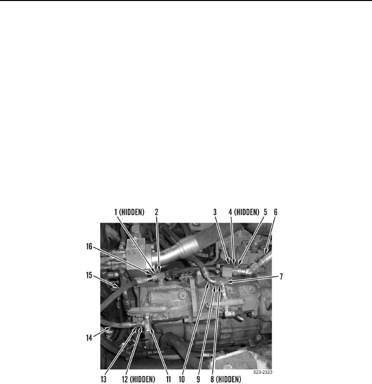
11. Loosen tube nut (Figure 7, Item 13) and remove hose (Figure 7, Item 14) and O-ring (Figure 7, Item 12) from
fitting (Figure 7, Item 11). Discard O-ring.
12. Loosen tube nut (Figure 7, Item 16) and remove hose (Figure 7, Item 15) and O-ring (Figure 7, Item 1) from tee
fitting (Figure 7, Item 2). Discard O-ring.
13. Loosen tube nut (Figure 7, Item 5) and remove hose (Figure 7, Item 6) and O-ring (Figure 7, Item 4) from tee
fitting (Figure 7, Item 3). Discard O-ring.
14. Loosen tube nut (Figure 7, Item 9) and remove hose (Figure 7, Item 10) and O-ring (Figure 7, Item 8) from
fitting (Figure 7, Item 7). Discard O-ring.
Figure 7. Hoses.
0177