
TM 5-3805-298-23-2
0177
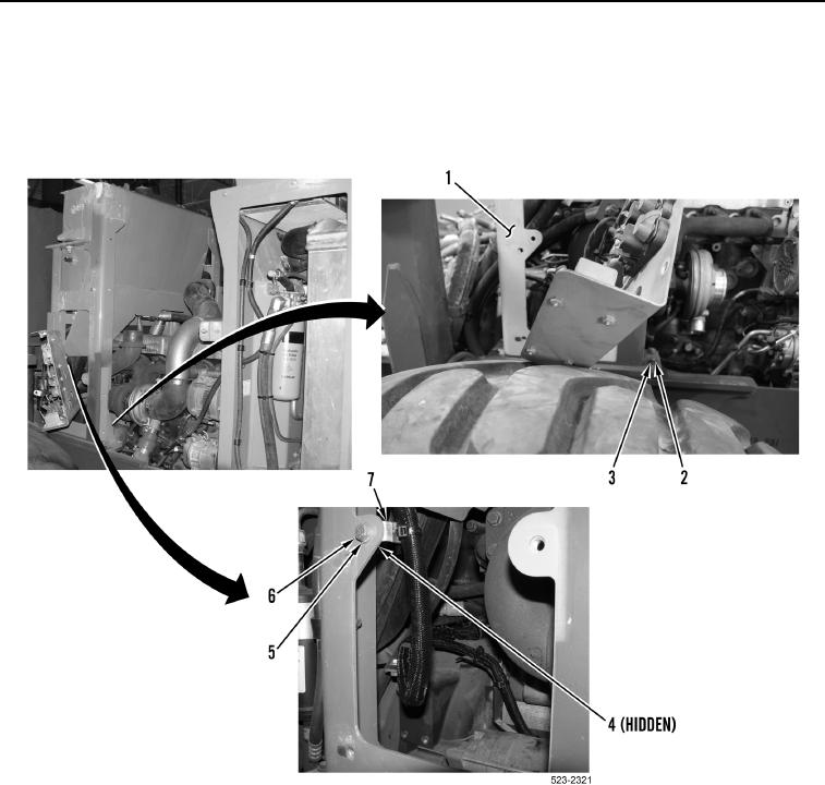
REMOVAL CONTINUED
7. Remove nut (Figure 5, Item 4), bolt (Figure 5, Item 6), two washers (Figure 5, Item 5) and ladder clip (Figure 5,
Item 7) from left hydraulic tank support bracket (Figure 5, Item 1).
8. Remove four bolts (Figure 5, Item 3), washers (Figure 5, Item 2) and left hydraulic tank support bracket
(Figure 5, Item 1) from machine.
Figure 5. Left Hydraulic Tank Support Bracket.
0177