
TM 5-3805-298-23-2
0177
REMOVAL CONTINUED
CAUTION
Cap all hydraulic openings along with component connections during removal to protect
against contamination. Failure to follow this caution may result in damage to equipment.
NOTE
Tag and mark all hoses and tubes to aid in installation.
Note routing of hoses and tubes for installation.
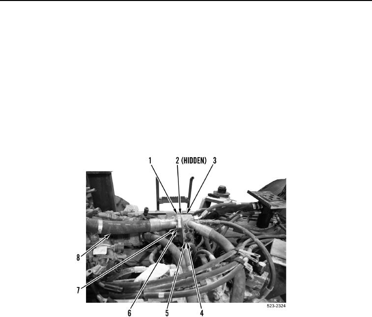
15. Remove four bolts (Figure 8, Item 7), washers (Figure 8, Item 6), split flanges (Figure 8, Item 1), hose
(Figure 8, Item 8) and O-ring (Figure 8, Item 2) from steering manifold (Figure 8, Item 3). Discard O-ring.
16. Remove four bolts (Figure 8, Item 4) and washers (Figure 8, Item 5) from steering manifold (Figure 8, Item 3).
Figure 8. Steering Manifold.
0177