
TM 5-3805-298-23-2
0178
INSTALL ENGINE ON STAND CONTINUED
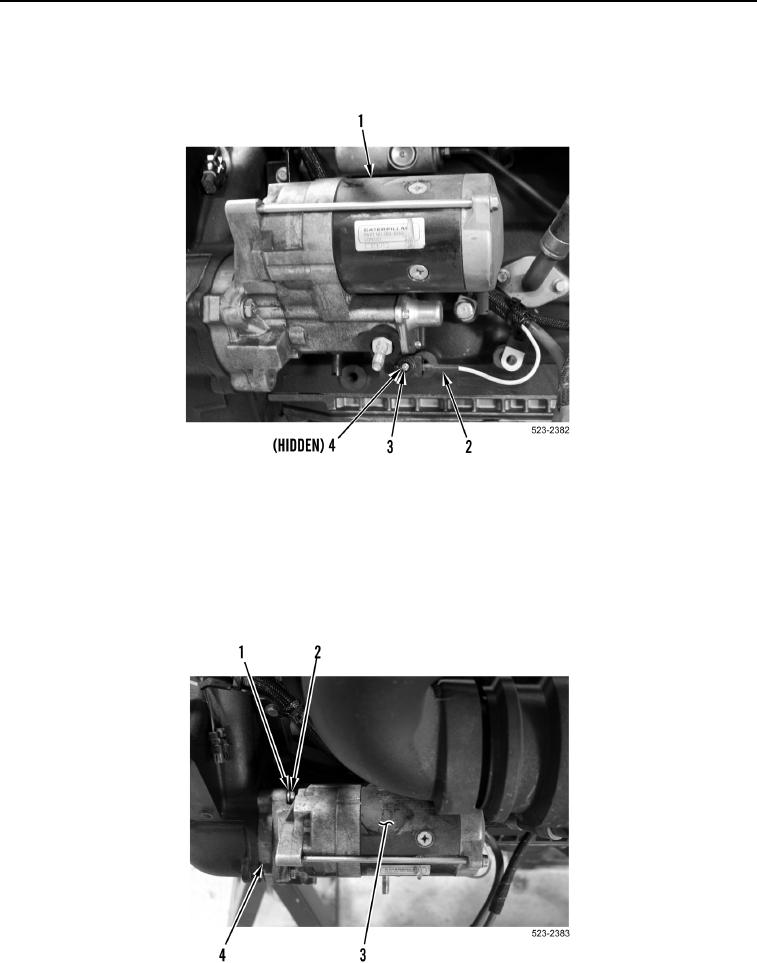
2. Remove screw (Figure 2, Item 3), lockwasher (Figure 2, Item 4), and wire harness connector (Figure 2, Item 2)
from starter (Figure 2, Item 1). Discard lockwasher.
Figure 2. Starter.
0178
NOTE
Note position and orientation of spacer for installation purposes.
3. Remove two bolts (Figure 3, Item 2), washers (Figure 3, Item 1), starter (Figure 3, Item 3), and spacer
(Figure 3, Item 4) from engine.
Figure 3. Starter.
0178