
TM 5-3805-298-23-2
0177
INSTALLATION CONTINUED
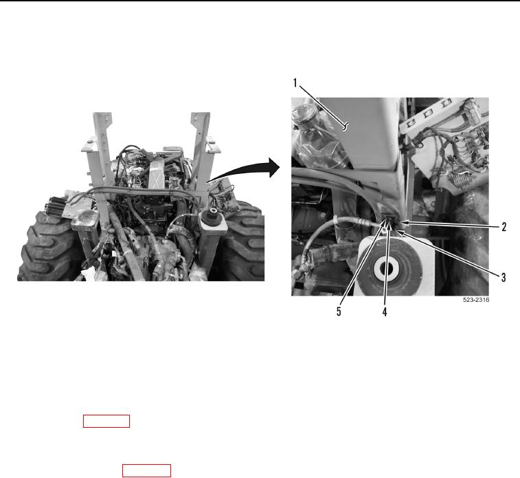
110. Install bracket (Figure 116, Item 3), P-clamp (Figure 116, Item 2), washer (Figure 116, Item 5) and bolt
(Figure 116, Item 4) on left hydraulic tank support bracket (Figure 116, Item 1).
Figure 116. Left Hydraulic Tank Support Bracket.
0177
END OF TASK
FOLLOW-ON TASKS
000177
1. Fill transmission oil (WP 0312).
2. Fill engine oil (WP 0191).
3. Install operator platform (WP 0343).
4. Install hydraulic tank (WP 0392).
5. Install aftercooler pipe (WP 0207).
6. Install cooling module (WP 0341).
END OF TASK
END OF WORK PACKAGE
0177-103/(104 blank)