• Home
  • Download PDF
  • Order CD-ROM
  • Order in Print
Figure 114. Right Hydraulic Tank Support Bracket.
Figure 116. Left Hydraulic Tank Support Bracket.

Field Maintenance Manual For 924H Wheel Loader -2 Page Navigation
  608    609    610    611    612  613  614    615    616    617    618  
img
.
TM 5-3805-298-23-2
0177
INSTALLATION CONTINUED
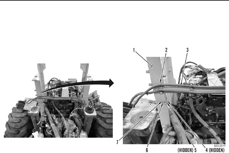
108. Position bracket (Figure 115, Item 3) on machine.
109. Install bracket (Figure 115, Item 3), two P-clamps (Figure 115, Item 2), washers (Figure 115, Item 7), bolts
(Figure 115, Item 6), washers (Figure 115, Item 5) and nuts (Figure 115, Item 4) on right hydraulic tank sup-
port bracket (Figure 115, Item 1).
Figure 115. Right Hydraulic Tank Support Bracket.
0177
0177-102


Privacy Statement
Press Release
Contact

© Copyright Integrated Publishing, Inc.. All Rights Reserved.