TM 5-3805-298-23-2
0179
REMOVAL CONTINUED
NOTE
Mark the direction of rotation if drive belt is to be reused.
Note drive belt routing to aid installation.
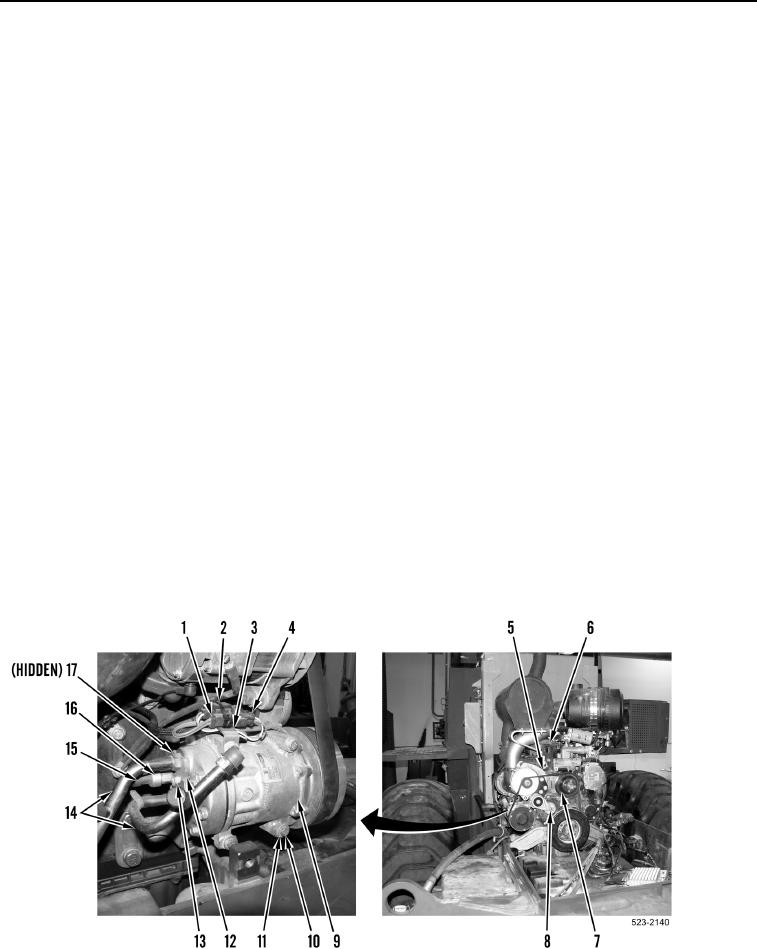
2. With assistance, rotate drive belt tensioner arm (Figure 2, Item 7) clockwise.
3. Remove drive belt (Figure 2, Item 5) from pulleys (Figure 2, Item 6).
4. Release pressure on drive belt tensioner arm (Figure 2, Item 8).
NOTE
Note quantity and location of tiedown straps to aid installation.
Tag and mark wiring harness connectors and note wiring harness routing to aid
installation.
5. Remove tiedown strap (Figure 2, Item 2) from A/C compressor clutch wiring harness (Figure 2, Item 1) and
ladder clip (Figure 2, Item 3). Discard tiedown strap.
6. Disconnect engine control wiring harness connector (Figure 2, Item 4) from A/C compressor clutch wiring
harness connector (Figure 2, Item 1).
7. Disconnect engine control wiring harness connector (Figure 2, Item 15) from A/C high pressure switch
(Figure 2, Item 16).
8. Remove bolt (Figure 2, Item 13), plate (Figure 2, Item 12), and two A/C lines (Figure 2, Item 14) from A/C
compressor (Figure 2, Item 9).
9. Remove four bolts (Figure 2, Item 10), washers (Figure 2, Item 11), ladder clip (Figure 2, Item 3), and A/C
compressor (Figure 2, Item 9) from machine.
10. Remove two O-rings (Figure 2, Item 17) from A/C compressor (Figure 2, Item 9). Discard O-rings.
11. Attach lifting device on engine lift bracket (Figure 2, Item 6).
Figure 2. A/C Compressor.
0179

