
TM 5-3805-298-23-2
0179
INSTALLATION CONTINUED
NOTE
Install washers and hardware as noted during removal.
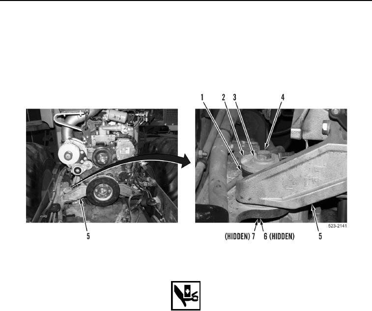
5. Install top engine mounts (Figure 7, Item 1), four washers (Figure 7, Items 2 and 3), two bolts (Figure 7,
Item 4), washers (Figure 7, Item 7), and nuts (Figure 7, Item 6) on engine mount brackets (Figure 7, Item 5).
Figure 7. Engine Lifting Device and Top Engine Mounts.
0179
WARNING
Use extreme caution when handling heavy parts. Provide adequate support and use
assistance during procedure. Ensure lifting device used is in good condition and of
suitable load capacity. Keep clear of heavy parts supported only by lifting device. Failure
to follow this warning may cause injury or death to personnel.
NOTE
Engine weighs approximately 1,563 lb (709 kg.).
6. Using lifting device, lower engine approximately 1/2 in. (12.7 mm) to frame.
7. Remove lifting device from engine lift bracket (Figure 8, Item 6).
8. Install two O-rings (Figure 8, Item 17) on A/C compressor (Figure 8, Item 9).
9. Install A/C compressor (Figure 8, Item 9), ladder clip (Figure 8, Item 3), four washers (Figure 8, Item 11), and
bolts (Figure 8, Item 10) on machine.
10. Install two A/C lines (Figure 8, Item 14), plate (Figure 8, Item 12), and bolt (Figure 8, Item 13) on A/C
compressor (Figure 8, Item 9).