
TM 5-3805-298-23-2
0179
INSTALLATION CONTINUED
NOTE
Route wiring harnesses and install wiring harness connectors as noted during removal.
Install tiedown straps as noted during removal.
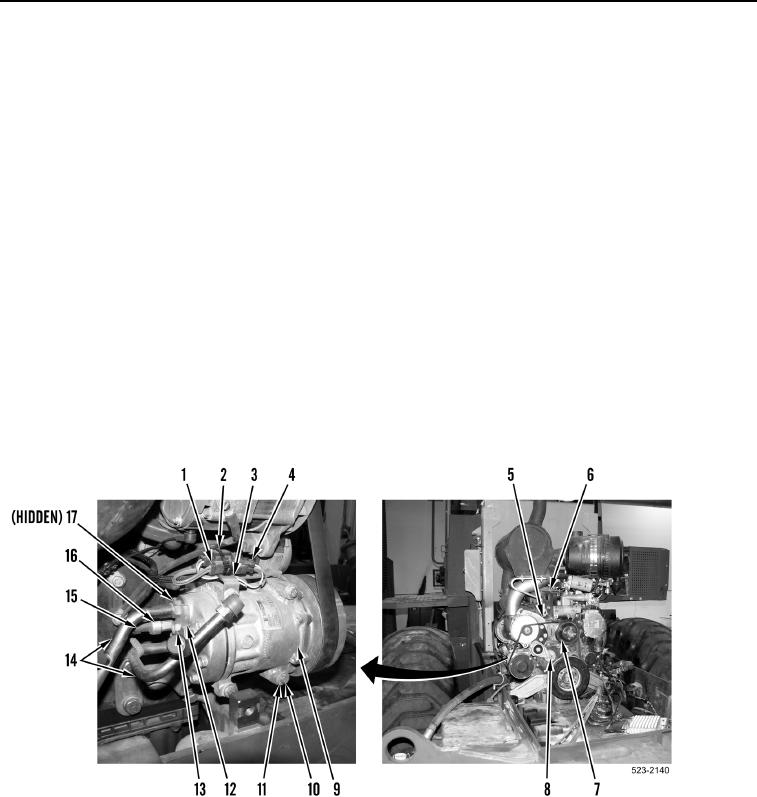
11. Connect engine control wiring harness connector (Figure 8, Item 15) on A/C high pressure switch (Figure 8,
Item 16).
12. Connect engine control wiring harness connector (Figure 8, Item 4) on A/C compressor clutch wiring harness
connector (Figure 8, Item 1).
13. Install new tiedown strap (Figure 8, Item 2) on A/C compressor clutch wiring harness connector (Figure 8,
Item 4) and ladder clip (Figure 8, Item 3).
14. With assistance, rotate drive belt tensioner arm (Figure 8, Item 8) clockwise.
NOTE
Install drive belt in correct routing as noted during removal.
Install in direction of rotation as noted during removal.
15. Install drive belt (Figure 8, Item 5) on pulleys (Figure 8, Item 7).
16. Release pressure on drive belt tensioner arm (Figure 8, Item 8).
Figure 8. A/C Compressor.
0179